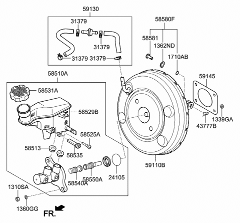
vacuum brake booster diagram
I need a vacuum diagram for a 2001 dodge ram 2500 4wd with the 8l v 102001 dodge ram 1500 4x4 vacuum hose diagram for the hoses to the 4 wheel drive. Vacuum diagram on 2002 Ram 1500 Hank OHop.

Vacuum Brake Booster Diagram Schematic And Image 01
Im having trouble fig out the vacuum lines from the 2 speed Powerglide and the factory ac.

. Hello here is a vacuum line diagram click the image below. Disconnect and label all vacuum lines to the carburetor noting those lines that run from the distributor spark delay valve temperature sensing valve EGR valve fuel vapor canister and so forth. Not only is a soft pedal annoying to deal with but also it can be a safety hazard.
Symptoms of a leaking brake booster include a hissing noise coming from the brake pedal area and lack of brake assist. 5A Speed sensor brake light switch brake booster relay. Step 1 - Prepare the Car.
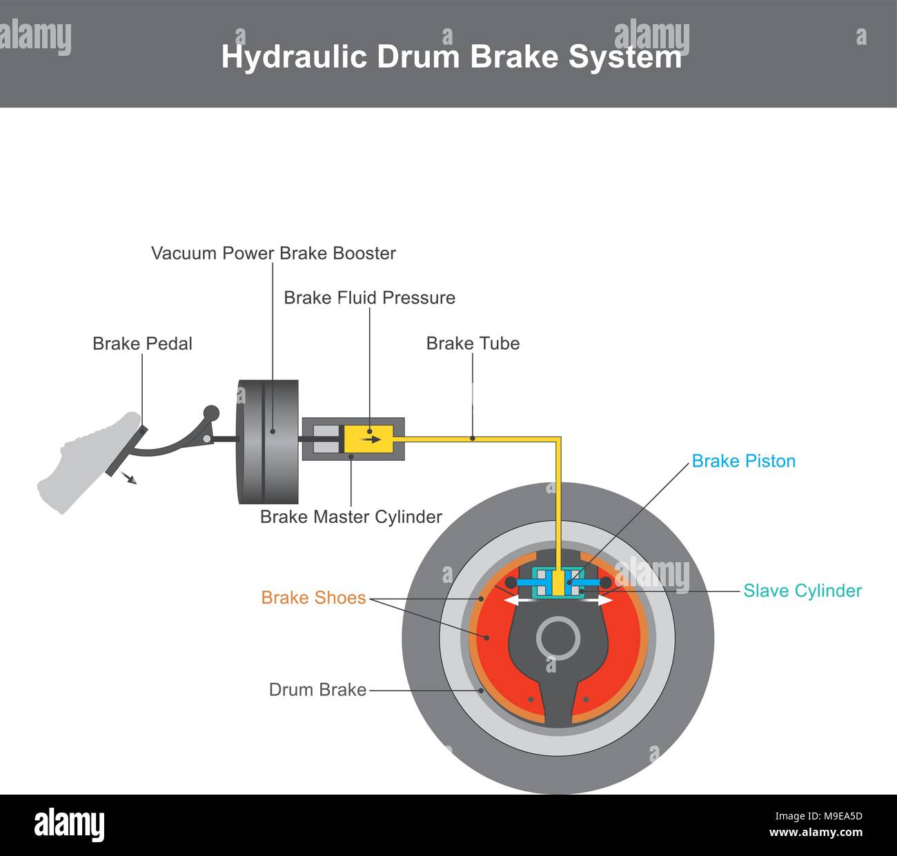
A hydraulic brake is an arrangement of braking mechanism which uses brake fluid typically containing glycol ethers or diethylene glycol. IDM Members meetings for 2022 will be held from 12h45 to 14h30A zoom link or venue to be sent out before the time. Brake Hose Kit Front and Rear 94-98.
Infineon can deliver it all and offers full-spectrum safety support and expertise. This is effected under Palestinian ownership and in accordance with the best European and international standards. The brake booster runs on engine vacuum to help make the brake pedal easier to push and easier to stop the tahoe.
F12 5A 20A Coolant circulation pump Ignition coil. Emission Systems Emission Control Vacuum Harness 40L ERH Engine Emission Systems Emission Control Vacuum Harness 52L ELF 59L EML Engine Sort by. Use Diagram 1 or 2 whichever applies to your.
The vacuum booster or vacuum servo is used in most modern hydraulic brake systems which contain four wheels. General arrangement diagram of control units. Front Brakes Disc Type Front Drum Brakes 1964 - 1984 - All Hydrolastic Dry Suspension 1964 ON.
Carefully disconnect the fuel line3. Use our handy classic Mini parts diagram to find the right part for your favorite little car This is the 1959 1989 parts diagram by Mini Mania. Rear control unit CL model.
Rear door control unit S Class. Power supply diagnostic pump Air mass meter Brake vacuum pump. 07 - 13 Lexus IS250 IS350 IS-F.
Remove the existing carburetor by the. Vacuum Control Pipes Ignition Cables Shields Alternator Dynamo Fittings. Wrap the end of the fuel line with a clean lint-free cloth.
Cottage on lake for sale near me. Place a 12 cap over the vacuum port on the manifold. Such as the electric brake booster thats specially designed for next generation brakes common to hybrid and electric cars.
The vacuum booster is a metal canister that contains a clever valve and a diaphragm. 2016 2017 2018 Jeep Grand Cherokee WK Brake Booster Vacuum Pump. Several manufacturers have issued recalls or.
For example a faulty brake booster will create a vacuum leak and youll have no way of telling just by looking. Select your vehicle options to narrow down results. I dont have the T fitting at the back of the manifold.
NEED A VACUUM DIAGRAM 1986-1987 300 E FOR THE ENGINE COMPARTMENT Save Share Reply Quote A. Npr Exhaust Brake Wiring isuzu npr exhaust brake wiring diagram 2007 w series chevrolet amp gmc n s i age 250 2007 gm isuzu truck 2007. EUPOL COPPS the EU Coordinating Office for Palestinian Police Support mainly through these two sections assists the Palestinian Authority in building its institutions for a future Palestinian state focused on security and justice sector reforms.
FREIGHTLINER COLUMBIA CL112 CL120 TRUCKS WORKSHOP SERVICE REPAIR MANUAL Oct 25 2016 2000 freightliner fl60 fuse panel diagram 4k wiki wallpapers 2018 2001 wiring freightliner business class m2 fuse boxM2 Fuse Box Location - Go To Work On A Wiring Diagram 1bdkozikidzdefuse box m2 location freightliner diagram columbia wiring. Lexus IS250 Lexus IS300 Lexus IS350 F Sport Club. The vacuum booster is attached between the master cylinder and the brake pedal and multiplies.
Vacuum Hose Routing Diagram Vacuum Hose Routing. I need some help or diagram for the vacuum lines on the 283 with factory ac. Hydro-Max Hydraulic Brake Booster and Master Cylinder Brake Booster Diagram Dave S Place Hydro Vac Info.
F6 5A 10A 15A Fuel System Diagnostic Pump Fuel Tank Shut-Off Valve Secondary Air Pump Relay. Step 3 Remove the master cylinder from the brake booster. Its a 90 and goes only to brake booster.
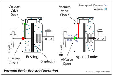
When a brake booster leaks it creates a vacuum leak. A rod going through the center of the canister connects to the master cylinders piston on one side and to the pedal linkage on the other. AdBlue Relay Additional Fan Charge Air Cooler Circulation Pump.
These bolt on kits mount to the original master cylinder-power booster mounting studs found on the firewall and use the factory pedal assembly. A leaking brake booster is a safety concern and must be replaced. Our 1973-87 Chevy and GMC truck power brake booster kits will help your truck stop better than ever.
入会を検討している道場へ問い合わせをします 全国支部検索 で道場を検索した場合は問い合わせ先の電話番号やメールアドレスが掲載されていますのでそちらへお問い合わせください よくある質問 もお読みなると良いでしょう 問い合わせ時に伝えること. Remove the power brake vacuum hose from the engine and the brake boosterInstall a new vacuum hose from the same engine vacuum source to the plastic check-valve on the tank. Remove the vacuum line from the brake booster.
When engineering your electric brake booster application what counts is having the right components available at the right time. ピアスに関するqa 販売しているピアスはすべて2個売りですか ピアスは2個売りとなっております 一部の特殊な形状のピアスや片耳用のピアスは1個売りとなっております. Door Control Unit Left Door N691.
Going over the vacuum lines on a. Cap placed on the intake manifold vacuum port. Use pliers to remove the vacuum line connected to the brake booster and intake manifold.
When a booster develops an internal leak you can hear the vacuum escaping through the leak when you step on the brakeThe engine stalls because the vacuum leak in the brake booster also causes a large vacuum leak for the engine. Replace 4 wheel drive vacuum actuator 1998 dodge ram 1500 4wd 4x4 duration. Learn how to adjust your brake systems push rod by following the steps below.
The cruise control takes its speed signal from a rotating driveshaft speedometer cable wheel speed sensor from the engines RPM or from internal speed pulses produced electronically by the vehicleMost systems do not allow the use of the cruise control. The good news is that the fancy. The driver must bring the vehicle up to speed manually and use a button to set the cruise control to the current speed.
Inside the brake booster there is a vacuum diaphragm. Rear door control unit.

Vacuum Brake Booster How It Works Animation Youtube

Agco Automotive Repair Service Baton Rouge La Detailed Auto Topics Vacuum Brake Boosters
Vacuum Power Brake Booster Hi Res Stock Photography And Images Alamy
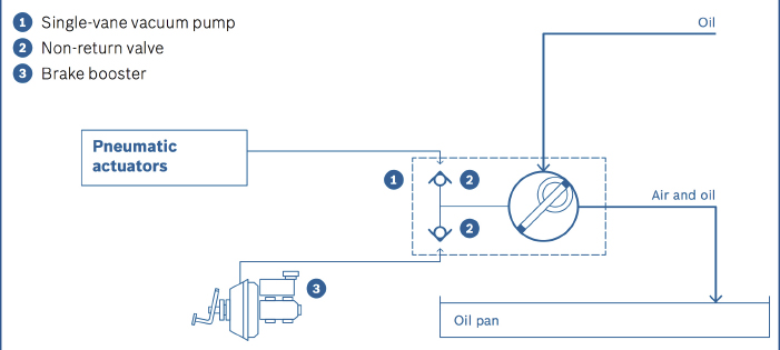
Vacuum Pumps For Brake Booster

Power Brakes Vacuum Assist Explained Youtube
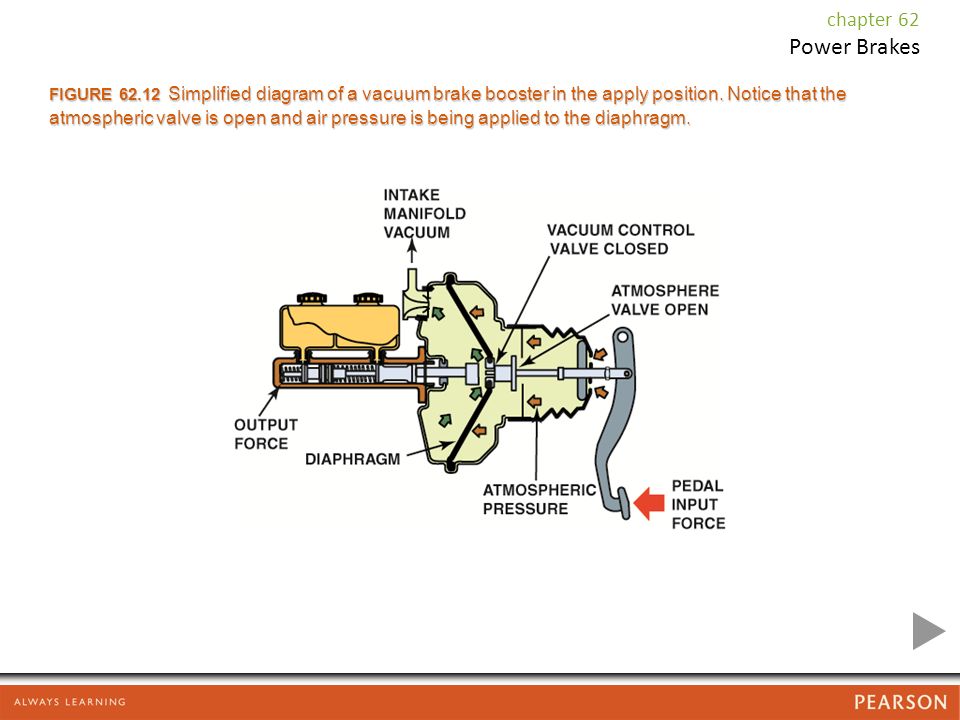
Power Brakes Chapter 62 Power Brakes Figure 62 1 Typical Vacuum Brake Booster Assembly The Vacuum Hose Attaches To The Intake Manifold Of The Engine Ppt Download

Diagram Of Vacuum Booster System Download Scientific Diagram

Power Booster

Diagram Of Vacuum Booster System Download Scientific Diagram
Vacuum Brake Booster Hard Pedal Problems Diagnosis
59130 3x200 Genuine Hyundai Hose Assembly Brake Booster Vacuum

Vacuum Brake Booster Power Braking System Construction And Working In Hindi Youtube

Power Brake Booster Diagram Crankshift
Diagram For Brake Booster Vacuum Sensor Lnf Df Kit Car Forum

Mechanical Technology Power Brakes Vacuum Booster And It Types

038 Brake Booster Vacuum Pump Parts Diagram For Ferrari 412 Maranello Classic Parts

Vacuum Power Assist Service